|
技术白皮书(一)—— 赤道仪摩擦传动技术分析Time:2024-11-12 在天体观测中,稳定且高精度的跟踪平台是必不可少的。历史上,许多著名天文台采用摩擦传动技术驱动望远镜,凭借其结构简单、跟踪平稳和高精度的特点,这种技术即使在当今的现代化环境中依然未被完全取代。经过对多种驱动传动形式的比较,我们愈发认为摩擦传动是赤道仪设计中最优美的呈现方式。 然而,民用领域对摩擦传动技术的探索仍显不足。为了推动这一技术的普及,本文将深入剖析摩擦传动系统中的正压力设计、摩擦系数选择及静摩擦与滚动摩擦之间的动态平衡,旨在消除爱好者对其的误解,并激励更多企业参与探索,从而为爱好者带来更多选择。
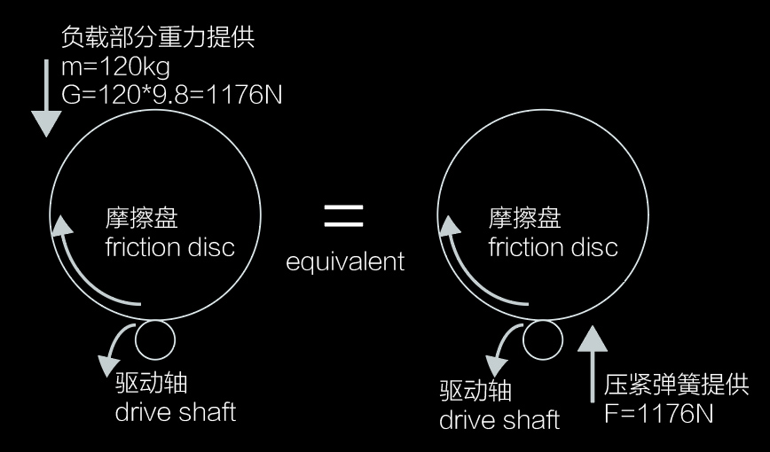
首先,需要确定赤道仪的压力附加形式。 例如,SFE300采用主动正压力设计,而SFE400使用复合正压力设计。在SFE300的摩擦传动系统中,RA轴的摩擦盘位置随仰角固定,意味着所承受的负载重量无法直接传递到驱动轴上。 根据牛顿第三定律,“力的作用是相互的”原则,我们将驱动轴施加的主动正压力应用于摩擦盘,从而形成等效经典的受力情况。
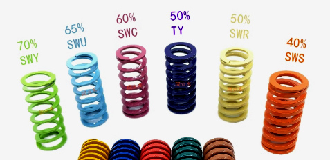
接着,我们来看看这个经典物理公式:最大静摩擦力 = 静摩擦系数μs × 正压力N 这里面只有两个参数 1、摩擦副材料或摩擦系数(如聚氨酯-钢、钢-钢和橡胶-钢等) SFE系列赤道仪选用了钢-钢摩擦形式,因为其刚性和持久保持的精度表现最佳。查表得知,钢-钢的摩擦系数范围为0.4-0.6。这里我们取0.4 2、正压力,那我们来看看如何确定合适的正压力。 正压力的下限计算 负载:为了满足60kg的载重需求,需计算整个转动部分的重量=60kg望远镜 + 50kg配重 + 10kg可动机械=120kg。 在SFE300中这个预紧力是通过四个矩形模具弹簧维持的。矩形模具弹簧具有优良的耐疲劳性能和稳定线性的弹性系数,能够长期可靠保持恒定的预紧力输出。
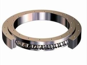
正压力的上限计算 轴承:SFE系列赤道仪的摩擦盘通常使用交叉滚子轴承,其静负载能力可达2吨以上。这里需以最弱的驱动轴轴承计算,2颗静负载能力3180N(约324kg),再折算2.5倍安全系数,约130kg。 材料:根据赫兹接触理论,局部压应力的计算结果表明,普通钢材无法在120kg正压力下(高达900Mpa)长期可靠工作。 因此,我们选择特种钢材辅以热处理工艺,其屈服强度超过1000MPa,以确保设备能够长期稳定运行。
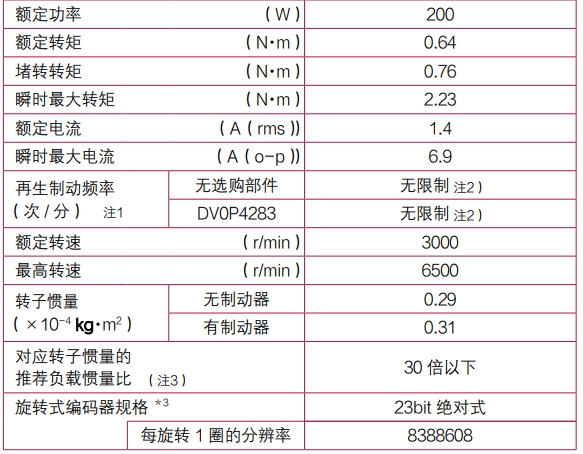
结论:综合考虑负载、轴承和材料的各方面因素,最终施加在摩擦副上的正压力定为120kg。此设置不仅确保了设备达到额定载重,而且能够长期稳定使用。 1.2静摩擦与滚动摩擦的基本概念 在摩擦传动赤道仪设计中,静摩擦和滚动摩擦之间的平衡至关重要。静摩擦力需足够大,以防止启动和负载变化时的打滑;同时,滚动摩擦力应尽可能降低,以确保系统在运行时的顺畅与高效。 所以在我们计算打滑的情况下是取用静摩擦系数,而计算旋转阻力的时候是采用滚动摩擦系数。两者有本质区别。接下来我们看看具体的计算方法: 以SFE300为例 摩擦形式:圆柱-圆柱 材料:钢-钢 接触长度:12mm 静摩擦系数 (μ静):0.4 施加正压力:120 Kg 摩擦盘半径:0.15 m 驱动轴半径:0.004 m 减速比:37.5 静摩擦部分: 根据公式计算:最大静摩擦力 = 静摩擦系数 × 法向力。对于钢-钢摩擦,静摩擦系数约为0.4。四个矩形弹簧30 × 4 = 120 kg 最大静摩擦力=120×9.8×0.4=470N 转化为扭矩 =0.15×470≈70Nm 滚动摩擦部分: 根据公式计算:最大滚动摩擦力 = 滚动摩擦系数 × 法向力.对于带有轴承的结构,滚动摩擦系数=0.005 滚动摩擦扭矩(大盘)=120×9.8×0.005=5.88N 转化为扭矩 =0.15×5.88≈0.88Nm 实际轴承内部油脂会极大增加这个滚动摩擦阻力,假设=5Nm,经过37.5倍减速后 转化为扭矩 =5/37.5≈0.13Nm 在120kg正压力下,静摩擦70Nm Vs 滚动摩擦0.13Nm。对于峰值扭矩超过2Nm伺服电机来说,0.13Nm的阻力也显得如此微不足道。 此结果表明,在120kg压力条件下,滚动摩擦阻力对电机扭矩的影响可以忽略不计。 1.3 电机与外部因素 除了摩擦因素,其他附加因素也可能导致打滑。例如,当输入的扭矩超过最大静摩擦力所能提供的额度时,打滑现象将会发生。这通常出现在电机加速度过快并且惯量无法匹配的情况下。 已知最大静摩擦力为70Nm,减速比为37.5:1,因此电机端的最大扭矩不应超过:70/37.5≈1.9Nm 换句话说,外界干扰力矩(例如风)若小于70Nm,伺服电机能够实时纠正位置而不会发生丢步。 伺服电机具备良好的力控特性,能够根据需求方便地设定力矩上限。具体而言,SFE300电机扭矩可在0.6~2.2Nm范围内调节,而SFE400电机的扭矩范围为1.3~4.4Nm,这样可有效避免打滑现象的发生。
有了这些深入的理解与合理的设计,我们能够在未来的应用中更好地优化赤道仪的性能,确保其在实际操作中达到预期的效果。 这些见解为进一步的改进和创新提供了基础,确保我们在设计和建造摩擦传动赤道仪时能够应对多种挑战,提升整体系统的效率与可靠性。 In astronomical observations, a stable and high-precision tracking platform is essential. Historically, many renowned observatories have utilized friction drive technology to operate telescopes. Due to its simple structure, smooth tracking, and high precision, this technology has not been completely replaced even in today’s modern environment. After comparing various drive mechanisms, we increasingly believe that friction drive is the most elegant design for equatorial mounts. However, exploration of friction drive technology in the civilian sector remains insufficient. To promote the widespread adoption of this technology, this paper will delve into the design of normal pressure in friction drive systems, the selection of friction coefficients, and the dynamic balance between static and rolling friction. The aim is to dispel misconceptions among enthusiasts and encourage more companies to participate in the exploration, thereby providing enthusiasts with more options. 1.1 Friction Force Requirements of Friction Drive Equatorial Mounts First, it is necessary to determine the method of pressure application for the equatorial mount. For example, the SFE300 adopts an active positive pressure design, while the SFE400 uses a compound positive pressure design. In the friction drive system of the SFE300, the position of the friction disc on the RA axis is fixed with respect to the altitude angle, meaning that the weight of the load cannot be directly transferred to the drive shaft. According to Newton's third law, which states that "the action of force is mutual," we apply the active positive pressure exerted by the drive shaft to the friction disc, forming an equivalent classical force situation. Next, let’s look at this classic physics formula: Maximum static friction force = Static friction coefficient μs × Normal pressure N. There are two parameters involved here: 1. Friction Pair Material or Coefficient (e.g., polyurethane-steel, steel-steel, and rubber-steel): The SFE series equatorial mounts utilize a steel-steel friction form, as it provides the best rigidity and long-term precision retention. According to reference tables, the friction coefficient for steel-steel ranges from 0.4 to 0.6. In this case, we will take 0.4. 2. Normal Pressure: Now, let’s see how to determine the appropriate normal pressure. Calculating the Lower Limit of Normal Pressure Load: To meet the 60 kg load requirement, the total weight of the rotating components needs to be calculated: 60 kg telescope + 50 kg counterweight + 10 kg movable mechanism = 120 kg. In the SFE300, this preload is maintained by four rectangular mold springs. These springs exhibit excellent fatigue resistance and a stable linear elastic coefficient, allowing for the reliable maintenance of a constant preload output over time. Calculating the Upper Limit of Normal Pressure Bearings: The friction discs of the SFE series equatorial mounts typically use crossed roller bearings, with a static load capacity exceeding 2 tons. For the weakest drive shaft bearing, two units with a static load capacity of 3180 N (approximately 324 kg) give a safety factor of 2.5, which allows for about 130 kg. Materials: According to Hertz contact theory, calculations of local compressive stress indicate that ordinary steel cannot work reliably under a normal pressure of 120 kg (up to 900 MPa) over a long period. Thus, we choose specially treated steel with a yield strength exceeding 1000 MPa to ensure the equipment operates stably over time. Conclusion: Considering the load, bearings, and material factors comprehensively, the final normal pressure applied to the friction pair is set at 120 kg. This setup not only ensures that the equipment meets its rated load but also allows for long-term, stable use. 1.2 Basic Concepts of Static and Rolling Friction In the design of friction drive equatorial mounts, the balance between static and rolling friction is critical. The static friction force must be large enough to prevent slipping during startup and load changes, while rolling friction should be minimized to ensure smooth and efficient operation of the system. Therefore, when calculating slip conditions, the static friction coefficient is used, while the rolling friction coefficient is applied when calculating rotational resistance. The two have essential differences. Next, let’s look at the specific calculation methods: Using the SFE300 as an example: Friction Form: Cylinder-Cylinder Materials: Steel-Steel Contact Length: 12 mm Static Friction Coefficient (μ_static): 0.4 Applied Normal Pressure: 120 Kg Friction Disc Radius: 0.15 m Drive Shaft Radius: 0.004 m Reduction Ratio: 37.5 Static Friction Part: Using the formula: Maximum static friction force = Static friction coefficient × Normal force. For steel-steel friction, the static friction coefficient is approximately 0.4. Four rectangular springs provide 30 × 4 = 120 kg. Maximum static friction force = 120 × 9.8 × 0.4 = 470 N Converted to torque = 0.15 × 470 ≈ 70 Nm Rolling Friction Part: Using the formula: Maximum rolling friction force = Rolling friction coefficient × Normal force. For structures with bearings, the rolling friction coefficient = 0.005. Rolling friction torque (large disc) = 120 × 9.8 × 0.005 = 5.88 N Converted to torque = 0.15 × 5.88 ≈ 0.88 Nm. The actual internal grease in the bearings greatly increases this rolling friction resistance, assuming = 5 Nm. After a 37.5:1 reduction, Converted to torque = 5 / 37.5 ≈ 0.13 Nm. At a normal pressure of 120 kg, static friction is 70 Nm vs. rolling friction of 0.13 Nm. For a servo motor with a peak torque exceeding 2 Nm, the resistance of 0.13 Nm is negligible. This result indicates that, under the condition of 120 kg normal pressure, the influence of rolling friction resistance on motor torque can be ignored. 1.3 Motor and External Factors In addition to friction factors, other external factors may also lead to slipping. For example, slipping occurs when the input torque exceeds the maximum static friction force. This is usually seen when the motor accelerates too quickly and the inertia cannot match. Given that the maximum static friction force is 70 Nm, with a reduction ratio of 37.5:1, the maximum torque on the motor side should not exceed: 70 / 37.5 ≈ 1.9 Nm. In other words, as long as the external disturbance torque (e.g., wind) is less than 70 Nm, the servo motor can correct its position in real-time without missing steps. Servo motors possess good force control characteristics, allowing the torque limit to be easily set according to demand. Specifically, the SFE300 motor torque can be adjusted in the range of 0.6 to 2.2 Nm, while the SFE400 motor's torque range is 1.3 to 4.4 Nm, effectively preventing slipping. With these thorough understandings and reasonable designs, we can better optimize the performance of equatorial mounts in future applications, ensuring they meet expected outcomes in practical operations. These insights lay the foundation for further improvements and innovations, ensuring that we can address various challenges in the design and construction of friction drive equatorial mounts, enhancing the overall system's efficiency and reliability. |


